The reactor design could provide a high. A bed section b freeboard section and c conical closure section with inlet cone.

Bubbling Fluid Bed Reactor With Electrostatic Precipitator Download Scientific Diagram
The mean pressure drops predicted by the three models agree quite well with each other.

. 4 heat transfer tubes. The development of a specialized zeolite catalyst for cracking heavy oil into various fractions enabled the com-mercialization of the FCC circulating fluidized bed. Design and construction of a fluidized bed by robert ryan mota bachelor of science california state polytechnic university pomona 2010 a thesis Bubbling fluidized bed reactor design.
2 bubble size control through small solid particle size or baffles. The reactor consists of three sections. This leads to costly needs for grinding lignocellulosic biomass.
Modeling the Bubbling Fluidized Bed Reactor BFB. A jet region around a single centrally arranged injector lance in a bubbling fluidized bed reactor is characterized by different parameters like. Before the reactor is started the catalyst pellets lie on a grate at the bottom of the reactor.
Bubbling fluidized bed gasifier BFBG can convert biomass and coal into value-added chemicals and gaseous fuels for transportation or electricity generation Understanding the parameters that affect the fluidization hydrodynamics Collect experimental data representative of optimum conditions and use it to develop numerical simulations. Bubbling Fluidized Bed Reactor 4. Ad Ion Exchange Adsorbents Chelation Catalysts Specialty Resins.
The bubbles appear to be very similar to gas bubbles formed in. A typical fluidized bed reactor. Ad Search Thousands of Catalogs for Fluidized Bed Reactor.
Reaction platform that is Fluidized bed reactor. Jurnal Teknologi Sciences Engineering 58 2012 8588 In the design of bubbling fluidized beds the distributor 110 pressure drop ΔPd is maintained within a range of 15 to 30 of 100 the bed pressure drop ΔPb 312. Principle Fluid Passes through Bottom with low velocity first to settle down the Solid Material on the Porous Plate called Distributor.
Octave Levenspiel Emeritus Professor Oregon State University During the Second World War the US had an urgent need to produce enormous quantities of aviation gasoline. 5 solids circulation systems. Behavior of fuel associated impurities under selected combustion and gasification conditions.
Bubbling Fluidization This type of fluidization has been called aggregative fluidization and under these conditions the bed appears to be divided into two phases the bubble phase and the emulsion phase. The most disadvantage with fluidized-bed reactors is that they require fairly little particles 23 mm to reduce heatmass transfer effects. A laboratory scale fluidized bed reactor was designed and fabricated successfully.
Search Thousands of Catalogs for Fluidized Bed Reactor. Part A gives general guidelines for the design of large commercial fluidized bed reactors with respect to the following aspects. Yellow acrylic nails ideas we Consider a few of the most modern solutions to style them from ombre to short nails coffin square and glitter designs In case.
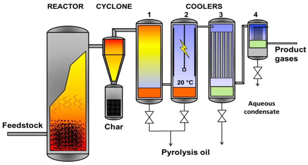
The pyrolysis of biomass starts in the bed reactor thanks to the high thermal exchange with the oxidant agent. Circulating fluidized bed reactor design and operation 39 --favourable turndown typically 41 and good load following capabilities. Gasoline and fluidized-bed reactors for making phthalic anhydride debuted in the 1940s.
The re-sults show a strong dependency on the restitution coefficient and the friction coefficient and no occurrence of bubbling and slugging for the ideal-collision case. 1 solids properties and their effect on the quality of fluidization. Eventually if the gas velocity is increased continuously it will eventually become sufficiently rapid to carry the solid particles upward out of the bed.
Due to increasing importance of treatment of wastewater in FBR critical examinations of the. The design of fluidized bed was based on empirical correlations fluidization and combustion. In Brownsville Texas in 1950 two large 5-m-diameter bubbling fluidized bed FischerTropsch reactors were built based on the results from a 03-m-diameter pilot plant operated with a Group B iron catalyst.
Fluid passes through the voids of the solid material. This is known as Packed Bed. Types Of reactor 1Bubbling Fluidized Bed 2Circulating Fluidized Bed 3Flash Reactor 4Annular Fluidized Bed 3.
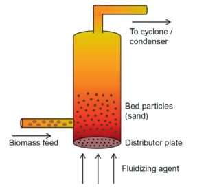
A fluidized bed reactor is a vessel partly filled with bed material sand and additives if any. This paper describes a pilot plant scale circulating fluidized bed unit recently designed constructed and put into operation in the Pulp and Paper Centre at the. When this begins to happen the bubbling and agitation of the solids are still present and this is known as the region of fast fluidization and the bed is a fast-fluidized bed.
At velocities beyond this region the particles are well apart and the. The bubbling fluidized bed is doubtless the foremost standard reactor for quick shift. The design parameters which affect the.
Bubbling beds of fine particles are difficult to predict and are less efficient Rapid mixing of solids causes non-uniform residence times for continuous flow reactors Particle comminuting breakup is common Pipe and vessel walls erode due to collisions by particles. 3 particle recovery by means of cyclones. Today about three-quarters of all polyolefins are made by a fluidized-bed process.
Bench scale fluidized bed reactor with lignite coal as the design fuel and to generate and study. The beds behavior after initial fluidization depends on. 1 19 Pb H mf Nyakuma et al.
The yields from the larger units were found to be disastrously less than those obtained in the pilot plant unit. Equipment Design The movie below shows the operation of a fluidized bed reactor. The disadvantages of fluidized beds are summarized below.
Lations on the fluidization behavior in a bubbling fluidized bed reactor. Fine particle fluidization the FCC process was proposed was chosen commercial plants were built. Bubbling fluidized beds are composed by a grid air-distribution at the bottom of the reactor to allow a good uniformity of the oxidant agent in the biomass particles avoiding thermal gradients along the radius of the reactor.
1 Bubbling fluidized bed reactor As is well known the bubbling fluidized bed reactor has become popular in the petrochemical industry for decades 119. As pyrolysis is endothermic in nature heat is supplied by heating the walls of the reactor and by. Fluidized bed reactors have been used and design for different physical and chemical process for example catalytic cracking fluid transportation and drying.
Reactants are pumped into the reactor through a distributor continuously causing the bed to become fluidized. New bubbling fluidized bed with vertically aligned vertical nozzles the fluid dynamics of the fluidized beds have to be determined and analysed especially the flow around the gas nozzles.
Bubbling Fluidized Bed Reactor Chemical Engineering World

Bubbling Fluidized Bed Reactor 76 Download Scientific Diagram
Bubbling Fluidized Bed Reactor Chemical Engineering World
Schematic Diagram Of A Bubbling Fluidized Bed Reactor Download Scientific Diagram

Bubbling Fluidized Bed An Overview Sciencedirect Topics

Process Schematic For Bubbling Fluidized Bed Download Scientific Diagram

Bubbling Fluidized Bed An Overview Sciencedirect Topics

Fluidized Bed Reactor Wikipedia
0 komentar
Posting Komentar